

OEM Stamping Parts Essentials for High-Quality Production
2026-11-16
Getting the right metal parts into production can feel like a guessing game—until you see what actually drives repeatable quality. At BOYIKUN, we treat OEM stamping as a precision process, not a commodity step. This guide breaks down the essentials that separate consistent, high-quality stamping output from costly trial and error.
Where Grain Direction Shows Up in Bend Consistency
The most visible clue is often at the press brake. When a sheet or blank is cut from stock without attention to rolling direction, two parts that look identical can settle at slightly different angles after forming. One bend hugs the tooling, another pulls back a degree or two. That spread is rarely random; it tracks with whether the bend line runs with or across the grain.
Grain direction also shows up in the radius and the surface. Bending across the grain tends to ask more of the outer fibers, so the radius may open slightly and springback becomes harder to predict. Bending with the grain can leave the outer edge looking rougher or dotted with fine cracks long before the part fails. In wood or laminate, the same principle appears as torn fibers on the outside of a curved piece when the grain runs parallel to the bend.
On the floor, the effect is practical. A batch of blanks with mixed grain orientation will not produce a consistent bend angle without constant adjustment. Sorting material so the bend line stays at a known orientation to the grain removes much of that drift. It is not that one orientation is always stronger; it is that orientation has to be held constant if consistency is the goal.
Reading Burr Height Before Dimensional Drift Appears
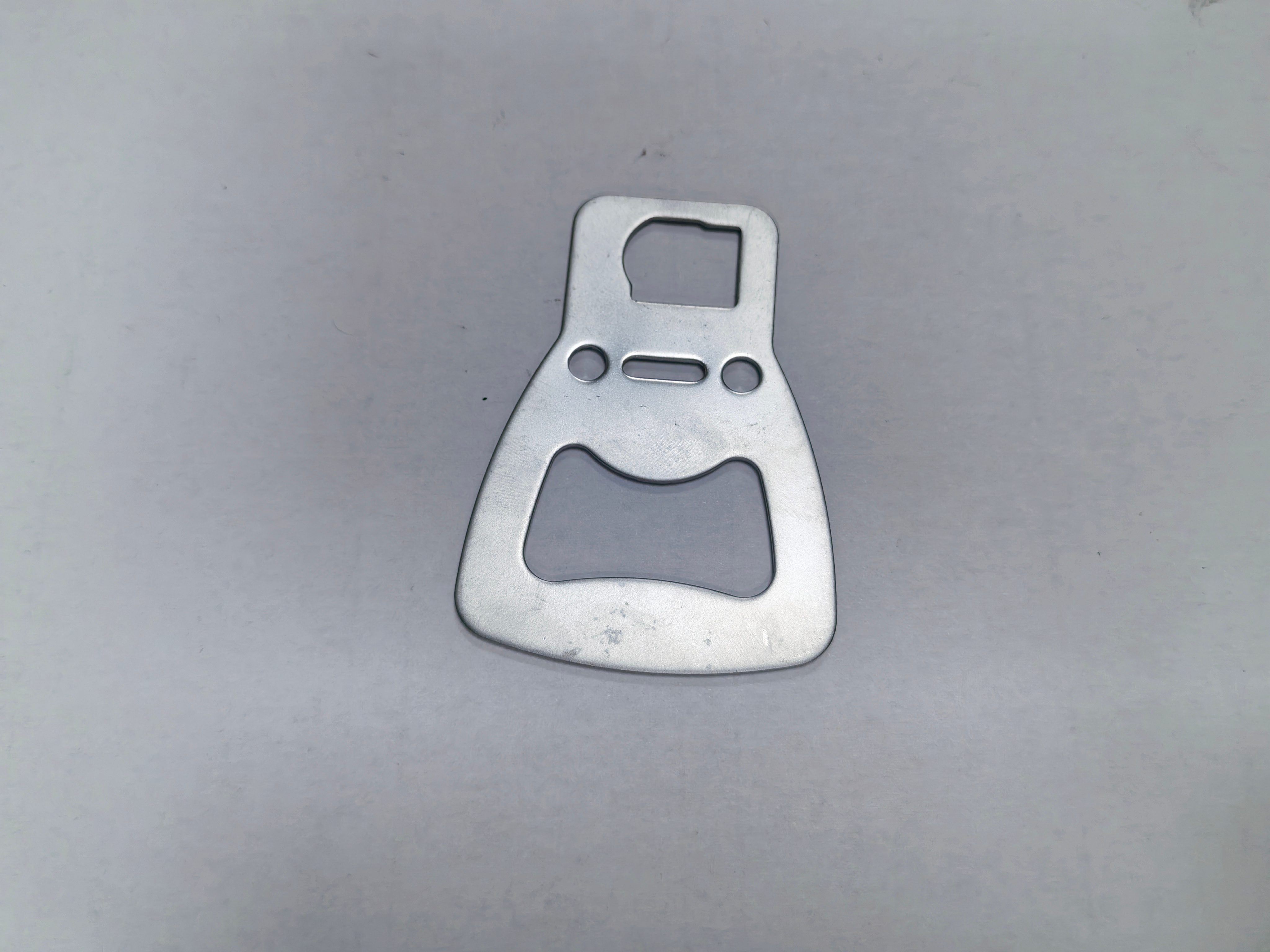
A burr rarely grows by accident. Long before a machined feature drifts out of tolerance, the edge condition often shifts in a repeatable way: the burr root thickens, the peak gets slightly taller, or the break-out zone changes shape. Tracking these small changes at a fixed inspection point gives a useful early warning that the cutting edge is starting to degrade.
Instead of waiting for a bore diameter or wall position to move, measuring burr height after a set number of cycles shows a more gradual trend. A worn edge pushes material rather than shearing it cleanly, so the surplus metal folds outward instead of separating. That change can appear several parts before a dimensional reading finally crosses the control limit.
The practical value comes from making the comparison local and consistent. Pick the same edge, the same orientation, and the same magnification each time. Even a modest rise of a few microns can signal climbing tool pressure and make corrective action worth taking now, while the part still has room to move.
Die Wear Schedules That Follow Part Data Instead of Calendars
A calendar cannot tell you when a punch has started to gall, but a sudden rise in tonnage on the third station of a progressive die often can. Maintenance teams that pull wear data from press monitors, part counts, and thickness checks are learning to schedule die service around the life the tool has actually lived. The date becomes a reminder to look at the numbers, not the reason to stop the line.
That shift changes the conversation with production as well. Instead of pulling a die every ninety days and finding it either lightly used or badly degraded, the data points to specific thresholds such as a jump in burr height, a drift in shut height, or a change in strip feed force. When those signals arrive, the die comes out for targeted work, and the usual blanket service tasks get rearranged around what the part data says is wearing.
There is also a quieter benefit on the shelf. Spare punch and die sections get ordered before failures because wear trends show the rate of degradation, not just the total count. A run of harder material may shorten the expected interval by several thousand strokes, and the schedule bends to match that reality. Over time the maintenance crew stops guessing about die condition and starts negotiating with the actual history of every part that passed through the tool.
Assembly Fit Problems That Start With Printed Tolerances
When a drawing specifies a tight tolerance, it is easy to assume the parts will simply fit together if the numbers look right on paper. In practice, printed tolerances only describe how far a single feature can deviate from its nominal size. They say almost nothing about how two mating features will behave once temperature, surface finish, and assembly sequence enter the picture. A shaft that measures within ±0.005 inches in a climate-controlled inspection room can bind in a housing on a warm shop floor, not because the tolerance was wrong, but because the fit was never analyzed as a system.
Most assembly fit problems begin quietly: the bore is at its low limit, the shaft at its high limit, and the resulting interference is still within the individual print tolerances. Designers often overlook form errors such as ovality or taper, which consume more of the tolerance zone than diameter variation alone. Fastener patterns introduce their own alignment constraints, and welded or bolted structures that are dimensionally correct before clamping can spring out of shape once the joints are torqued. These real-world effects mean that two parts can each pass final inspection and still refuse to go together cleanly on the line.
The fix is not to tighten every tolerance, which drives up cost without addressing the root cause. It is to treat the assembly condition as its own requirement. Stack-up calculations that include form, orientation, and realistic temperature ranges expose clearance risks before tooling is built. Prototype builds using parts deliberately produced at worst-case extremes reveal whether a fit can tolerate the full band or whether a selective assembly strategy, a floating fastener condition, or a slight redesign is needed. When printed tolerances are used as a starting point rather than a guarantee, the fits that matter most become far more predictable.
Why Small Setup Adjustments Shift Whole Batch Results
A half-turn on a dosing dial or a slight change in how a hopper is loaded might not seem like much until you see the first few units come off the line. Small setup adjustments often move results in ways that are easy to miss at the start and expensive to notice later. Because early settings influence pressure, timing, temperature, or fill level across the entire run, a tiny shift at setup doesn't stay tiny—it repeats in every single piece.
Most batch variation isn't caused by one large mistake. It comes from stacked micro-changes: a clamp tightened differently, a sensor wiped a few seconds longer, a mold aligned by eye instead of by jig. These adjustments change how materials settle, how heat transfers, or how fast a cycle begins to stabilize. Once the run is underway, those early conditions become the baseline, so every later stage inherits the same small error.
The practical takeaway is to treat setup not as a checklist to rush through but as the first few minutes of the batch itself. Recording exact positions, using the same hand pressure, and confirming the first outputs against a known reference all help. When results start drifting batch to batch, it's often not the raw material or the equipment—it's a small choice made before the process really started.
Post-Inspection Handling Steps That Keep Geometry Intact
Once the inspection data lands in your software, hold off on global remeshing or broad smoothing passes. Lock down the reference features first—datum planes, bore centers, and mating edges—and keep them fixed while you clean up noisier areas. Small, local patches that follow the surrounding curvature will preserve the part's intent far better than a single automatic cleanup operation.
For holes, slots, and sharp transitions, rebuild boundaries from measured cross-sections instead of letting a fill algorithm guess the shape. If the scan includes thin walls or tight fillets, use the original CAD or a stable neighboring surface as a guide, and check deviation after every few edits rather than waiting until the end. That keeps the correction process from drifting into a form that looks smooth but no longer matches the functional surfaces.
Finally, compare the processed model back to the raw inspection points with a local deviation map, not just a global average. Focus on mounting faces, seal grooves, and alignment features. If those areas have shifted beyond tolerance, undo the last modification and handle the region with a constrained fit. Leaving critical geometry untouched is often more valuable than producing a perfectly watertight mesh.
FAQ
The base metal largely dictates how the part behaves under load, how easily it forms without cracking, and how well it tolerates secondary operations like welding or plating. Skipping a careful grade review often leads to springback problems or premature tool wear.
Because every station in a progressive die adds slight variation, and thin sheet metal moves during forming. A tolerance that looks reasonable on paper can force unnecessary secondary calibration or raise scrap rates once the strip hits production speed.
A well-built die balances cutting clearance, pilot location, and draw radii so the material flows the same way on every stroke. When those details are ignored, you see burr height drift, hole position shift, and surface scoring after a few thousand cycles.
Surface condition affects friction during forming, coating adhesion, and even fatigue life in service. For OEM work, a specified roughness or grain direction can be just as important as dimensional accuracy, especially when parts are visible or painted.
If volumes are uncertain or the product is likely to change within a year or two, modular or adjustable tooling can absorb minor revisions without cutting a brand-new die. It usually costs more upfront than a simple line die, but it can avoid a full retooling expense later.
Material certification and batch traceability. Teams focus on dimensions and fit, but if the prototype was run from a different coil or heat lot than production, the approved sample may not represent what actually ships.
Small geometry changes, like adding a relief notch, adjusting a bend radius, or shifting a hole away from a bend line, can make the part much more stable to produce. Good suppliers look for those adjustments early, before tooling is cut.
Conclusion
High-quality OEM stamping rarely hinges on a single inspection number. Grain direction is the kind of variable that escapes attention at the quoting stage and then reappears as uneven bend angles or inconsistent springback across a run. When blanks are nested only for material utilization, the resulting grain orientation can vary from blank to blank, and the press operator ends up fighting scatter that no amount of shut height adjustment will fully correct. The early signs of trouble are often visible in burr height before any dimensional drift appears. A steady increase in burr height, or a change in its distribution along the cut edge, usually means the punch-die clearance is opening up or the cutting edges are beginning to round. Reading that signal early avoids producing parts that still measure in tolerance but are already moving toward the edge of the band. Die wear schedules are more reliable when they come from this kind of part data instead of a calendar. Tracking burr growth, surface finish, and tonnage changes lets maintenance happen when the tool actually needs it, not because a certain number of weeks have passed.
Many assembly fit problems start with printed tolerances rather than actual forming errors. A part can pass every callout on the drawing and still not seat correctly in the mating component because the tolerances were assigned independently, without a full stack-up that includes clamp load, weld distortion, or flex in the assembled state. In that sense, the print can be both correct and misleading at the same time. Small setup adjustments also carry more weight than they appear to. Pad pressure, feed timing, lubrication coverage, or even a small change in coil tension can move the whole batch average, but the impact may only show up after a couple hundred parts have already been stamped. Post-inspection handling is the last place those gains can be lost. If parts are stacked against edges, rested on non-critical surfaces, or shipped in worn dunnage, flanges and datum features can shift after final inspection. Supporting parts at the same contact points used during inspection and isolating critical surfaces through packaging keeps the geometry intact until the part reaches the customer.
Contact Us
Contact Person: Xianchen Hu
Email: [email protected]
Tel/WhatsApp: 86-13248645200
Website: https://www.hexnb.com/