

Reliable Through Hole Resistors: Choosing the Right One for Your Circuit
2026-07-21
In the world of electronics, where precision and stability are paramount, through hole resistors remain a trusted workhorse despite the rise of surface-mount technology. Whether you're prototyping a sensitive analog circuit or building a rugged power supply, choosing the right through hole resistor can make or break your design. But with so many options available, how do you navigate the key specifications like power rating, tolerance, and temperature coefficient? And where does reliability truly come from? At Milliohm, we understand that the devil is in the details—especially when it comes to resistive components. In this post, we'll guide you through the essential factors to consider, helping you select resistors that deliver consistent performance and long-term reliability in any project.
Decoding the Resistor: More Than Just Resistance
Often seen as the wallflowers of circuitry, resistors quietly dictate the rhythm of electrons in ways that extend far beyond a simple ohm value. Their influence seeps into the subtle art of thermal management, where the choice between a carbon film and a wirewound part can mean the difference between a stable amplifier and a drifting mess. The physical construction carries its own narrative—helical cuts in metal oxide create tiny inductances, turning a humble voltage divider into an accidental filter at high frequencies. Ignoring these quirks invites noise, distortion, and unexpected headaches into even the most meticulous design.
Temperature coefficients and voltage ratings weave another layer of complexity, transforming the resistor from a passive lump into an active participant in circuit behavior. A precision analog front-end might demand thin-film resistors with a drift so minimal it challenges measurement gear, while a pulse-handling snubber network relies on the bulk mass of a carbon composition part to soak up transient energy without flinching. Every material—from cermet to tantalum nitride—tells a story of compromise between stability, cost, and parasitic effects, forcing engineers to peer past the datasheet’s bold print.
The resistor’s quiet footprint also shapes board layout in ways that ripple through signal integrity. Guard rings, creepage distances, and thermal reliefs evolve around these components, dictating placement rules that can make or break a mixed-signal design. Even the humble 0402 chip resistor becomes a waveguide stub at multi-gigahertz speeds, its terminals radiating energy like tiny antennas. Decoding the resistor, then, is an exercise in seeing the invisible—uncovering the second-order effects that turn a simple three-band color code into a key that unlocks robust, real-world electronics.
Carbon, Metal, or Wire: How Construction Shapes Performance
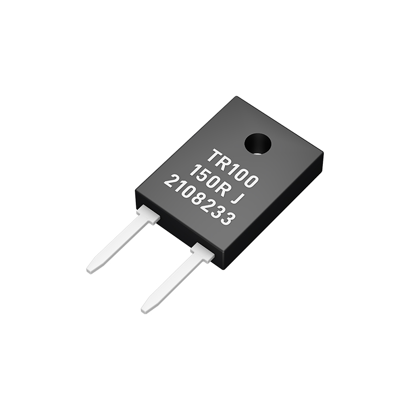
Every material brings its own personality to a product, but it's the way that material is arranged that often matters most. Consider a bicycle frame made from carbon fiber. The individual strands can be laid down in precise orientations to resist the twisting forces of pedaling, while remaining compliant enough to absorb road vibrations. The construction method allows a designer to place stiffness exactly where it's needed, something that would be impossible with a simple metal tube. The result is a structure that feels alive beneath a rider, responding with a snap that belies its light weight. It’s not just the carbon—it’s the thoughtful layering that transforms a bundle of brittle filaments into a resilient, high-performance frame.
Metal, on the other hand, has a reputation for predictability, but its performance can be drastically altered by the shaping and joining techniques used. Take a steel guitar string. The same piece of wire, when wound with different tensions or paired with a specific core shape, can produce a bright, clear twang or a deep, mellow hum. In architecture, a mild steel beam gains entirely new load-bearing capabilities when fabricated into an open-web truss. It’s a reminder that metal’s inherent strength is only half the story; the real magic happens when it’s bent, braided, or welded to redistribute stress along unconventional paths.
Then there’s wire, which might seem humble until you see it in the right arrangement. A single copper filament carries a negligible current, but bundle thousands of them into a Litz weave, and suddenly you have a conductor that handles high frequencies with dramatically reduced loss. The performance leap comes not from chemistry but from construction—the geometric precision of twisting each strand just enough to equalize current flow. Even in the world of medical devices, the pliability of a guidewire is engineered through its layered coil design, enabling it to snake through tortuous blood vessels without kinking. In every case, the raw material is merely a starting point; it’s the invisible language of construction that truly shapes what a thing can do.
Tolerance and Temperature: The Specifications That Sneak Up on You
You’ve picked the perfect op-amp, double-checked the bias currents, and simulated your circuit into perfection. Yet, when the first boards come back, the performance is all over the place. The culprit? Small print in the datasheet you skimmed: tolerance and temperature drift. These aren’t the glamorous specs, but they quietly define how your design behaves outside the lab bench.
Consider a simple voltage reference with a ±2% initial tolerance and a 100 ppm/°C temperature coefficient. Over a 50°C temperature swing, that’s an additional 0.5% error, stacking on top of the factory spread. In a 12-bit ADC system, that can eat up several LSBs before you’ve even started. Now multiply that across multiple components—resistor dividers, offset voltages, gain errors—and the cumulative effect can push a design from “marginally stable” to “downright flaky.”
What makes these specs so sneaky is that they don’t show up in a typical bench test at room temperature with fresh components. They lurk in the corners of the operating envelope, waiting for a cold startup or a heat-soaked enclosure. Getting a feel for the worst-case error budget early, and breadboarding across temperature, turns “spec surprise” into just another design parameter you’ve already tamed.
Power Ratings: Why Size Really Does Matter
It’s tempting to believe that power ratings are just arbitrary numbers stamped on a label, but the physical footprint of a device often tells a truer story. Larger components—thicker windings, more robust cooling fins, heavier-duty connectors—don’t just handle more current; they sustain it without degradation. A compact unit might punch above its weight for a few seconds, yet when demand remains high, only real mass and surface area can dissipate heat effectively enough to avoid throttling or outright failure.
The relationship between bulk and endurance becomes especially clear in audio amplification or industrial motor drives. Here, a higher rating isn’t always about peak wattage—it’s about continuous, stable output. A transformer that’s twice the size of its rival rarely delivers double the instantaneous power, but it will keep humming along at near maximum long after the smaller one has tripped its thermal protection. That difference isn’t just a spec on paper; it’s the margin between a reliable workhorse and a fragile overachiever.
Even when materials and topologies evolve, the physics of heat and magnetic saturation remain stubbornly scale-dependent. You can shrink control circuits onto a single chip, but you can’t miniaturize the copper and iron needed to push real watts without cooking the whole assembly. So next time you compare two devices with seemingly similar numbers, weigh them—literally. Heft is a surprisingly honest clue to how much sustained grunt lives inside.
Noise and Long-Term Drift: Overlooked But Critical
When evaluating sensor performance, most discussions center on sensitivity and range, but two quieter culprits—noise and long-term drift—often determine real-world reliability. Electrical noise introduces random fluctuations that can bury small signals, making it impossible to detect subtle changes or leading to false triggers. Drift, on the other hand, is a slow, insidious shift in baseline readings over time, caused by aging components or environmental exposure. Together, they erode measurement credibility in ways that are easy to miss during short-term lab tests.
The trouble is that noise and drift don't always announce themselves with obvious failures. In a production environment, a sensor might pass initial calibration only to develop a persistent offset weeks later, skewing data without triggering an alarm. High-frequency noise might be filtered out, but the real danger lies in low-frequency wandering that mimics actual trends. Engineers who treat drift as a minor inconvenience often discover its true cost when control loops start oscillating or safety thresholds are breached without warning.
Addressing these issues requires a mindset shift from spot-checking accuracy to continuous validation. Simple solutions like temperature-compensated references, periodic auto-zeroing, or dual-sensor voting can dramatically improve long-term stability. In the end, the most overlooked parameters are often the ones that silently dictate system success, reminding us that a sensor's datasheet only tells half the story.
Picking the Perfect Part: Rules Your Circuit Will Thank You For
Component selection isn’t just about matching a schematic symbol. It’s where your design’s reliability and performance really take shape. Start by looking beyond the nominal specs—consider how the part behaves across temperature swings, voltage variations, and aging. A resistor’s tolerance might drift under load, or a capacitor’s value might plummet near its rated voltage. Datasheets hide these traps in fine print; ferret them out before they sabotage your prototype.
Mechanical reality bites hard when you ignore it. That tiny SOT-23 package might run within thermal limits on paper, but put it next to a hot voltage regulator and things get ugly fast. Always derate for heat, leave breathing room, and double-check that your footprints match the actual component—not just the generic library version. And don’t forget assembly: a component that requires hand-soldering finesse when you’re building a thousand boards is a recipe for silent failure.
Obsolescence is the quiet killer. That perfect op-amp you found might be a lone-sourced, end-of-life part sitting on a dusty shelf. Unless you enjoy redesigning layouts mid-project, pick parts with at least two viable suppliers and a published lifecycle commitment. A few extra minutes upfront vetting availability and second sources saves you from ugly board spins and awkward conversations with procurement later.
FAQ
Reliability in through hole resistors comes from their robust physical construction—leads are firmly anchored in the board, providing excellent mechanical stability and resistance to vibration and thermal cycling. This makes them less prone to solder joint fatigue compared to surface mount parts, especially in high-stress environments.
Start by analyzing your circuit’s voltage and current requirements using Ohm's law, then add a safety margin. For tolerance, don't automatically choose 0.1% if 1% will do—tighter tolerances increase cost and can limit availability. Reserve precision resistors for feedback networks or reference circuits where accuracy directly impacts performance.
Wirewound parts excel in high-power, pulse-handling scenarios due to their thermal mass and surge tolerance. Go for metal film when you need low noise, tight tolerance, and stable resistance over time. The trade-off: wirewound can introduce unwanted inductance, so avoid them in high-frequency signal paths.
The power rating indicates how much heat the resistor can dissipate without damage. A common pitfall is ignoring ambient temperature—most ratings are at 25°C, but at 70°C you may need to derate by 50%. Always calculate actual power dissipation (I²R) and multiply by at least 1.5 for a safety factor, especially in enclosed spaces with limited airflow.
The temperature coefficient (TCR) tells you how much the resistance drifts with temperature. For a voltage divider that needs consistent output across a 0–60°C industrial range, a low-TCR metal film (e.g., ±50 ppm/°C) is essential. In contrast, a pull-up resistor on a digital input might tolerate ±200 ppm/°C without issue. Think of TCR as an error budget: every degree of change eats into your accuracy.
Leaving long leads can act as antennas and introduce noise; they also increase thermal resistance by reducing conduction to the board. Always form leads to keep the resistor body off the PCB to allow airflow, but avoid sharp bends near the body—stress there can crack the ceramic core. For high-vibration environments, consider using a bead of RTV silicone to dampen mechanical resonance.
Conclusion
Selecting a through-hole resistor for a reliable circuit goes far beyond picking a value from a bin. The material and construction define how it behaves under stress: carbon composition parts handle pulses well but drift with moisture and temperature, while metal film types offer tighter initial tolerances and lower noise—critical when tiny signals are involved. Wirewound resistors excel in precision or high-power roles, but their inductance can destabilize sensitive loops. Don't let the datasheet fool you into focusing only on ohms; parameters like the temperature coefficient and rated tolerance interact with your environment to shift the operating point over time, so a 1% resistor isn't truly 1% once the board heats up.
Physical size directly ties to power handling, and a part that's too small will silently degrade, risking open circuits. What's less obvious is that noise—often ignored until a prototype fails—can swamp analog stages, especially in high-gain nodes where carbon's inherent grain noise becomes the limiting factor. Long-term drift, accelerated by humidity or thermal cycling, turns a stable reference into a calibration nightmare. The safe bet? Derate generously, match the element type to the actual circuit demands (not just cost), and verify the real-world behavior of your chosen resistor in a prototype run. A handful of data-driven decisions here pays back in years of trouble-free operation.
Contact Us
Contact Person: Yuying Gao
Email: [email protected]
Tel/WhatsApp: +86 18926013721
Website: https://en.milliohm.net/