

Six-Motor Fiber Fusion Splicer Factory Standards Behind Precision Optical Connections
2026-09-04
In optical fiber networking, a fusion splicer is only as reliable as the precision behind its alignment system. Six-motor control has quietly become the gold standard for repeatable low-loss splices, yet few outside the factory floor understand why. Inside DVP production lines, that six-motor architecture isn't just a spec sheet bullet—it's a disciplined set of manufacturing tolerances, calibration routines, and stress tests that separate dependable field tools from costly compromises. This post pulls back the curtain on those factory standards, revealing how they translate into the clean, consistent optical connections that backbone networks demand.
Six Motors, One Goal: Zero Micron Drift
Each of the six motors operates with its own encoder loop, but they are not running independently in the usual sense. A central motion controller cross-checks position data every few microseconds, so a deviation in one axis is corrected by subtle adjustments in the others before it can turn into drift.
Chasing zero micron drift forces some uncomfortable engineering decisions. The frame is deliberately overbuilt, the bearings run preloaded, and temperature sensors feed into a real-time offset model. These are not features you can see from outside, but they are why the stage holds its position after hours of operation.
On a wafer inspection line, this translates to fewer mid-batch recalibrations. Operators can set a reference point at the start of a shift and trust that the six-motor stack will return to it within a fraction of a micron—even after thousands of back-and-forth moves.
The Calibration Room Where Every Splicer Earns Its Specs
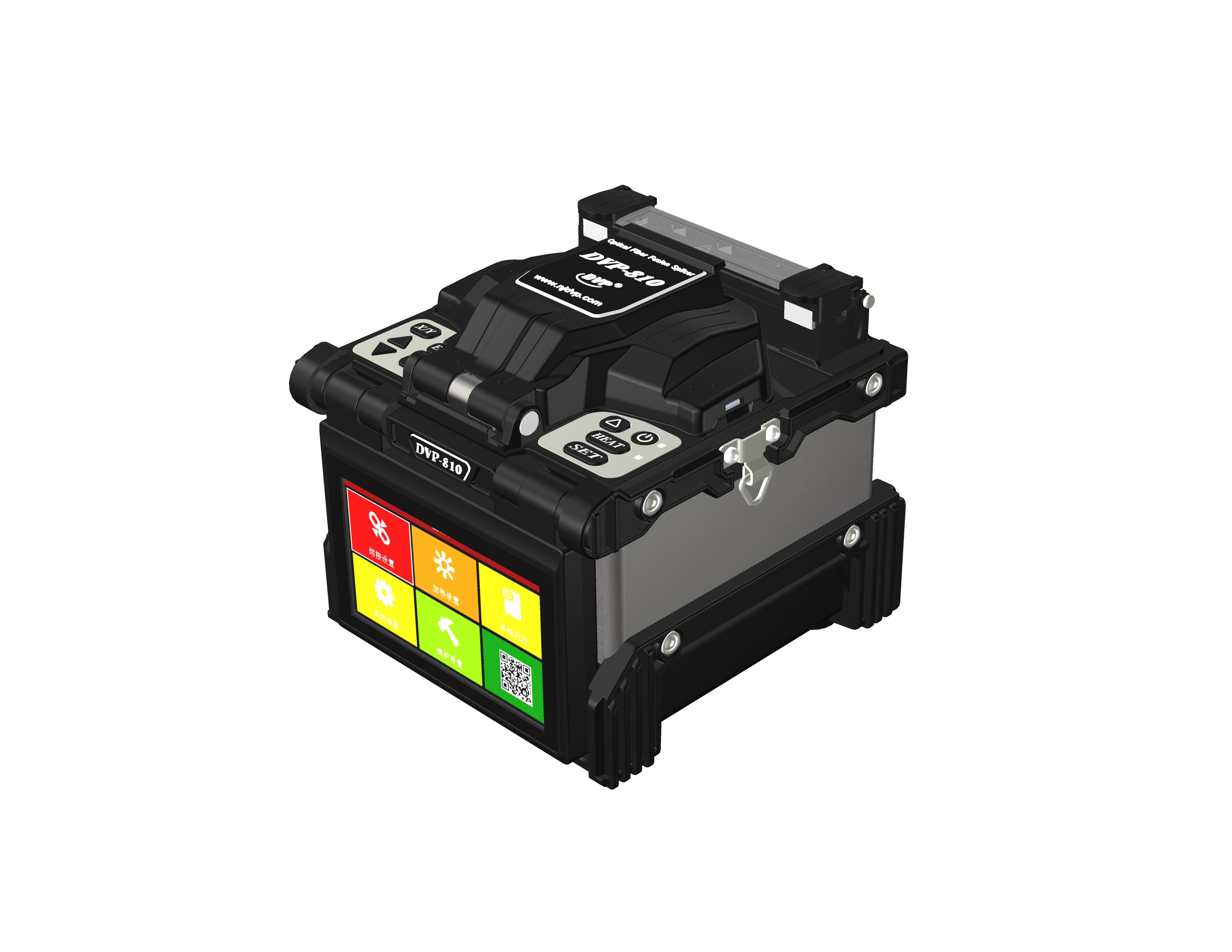
Inside the calibration room, rows of splicing machines sit under steady, shadowless light, each one wired to a reference standard that hasn't drifted in years. Technicians move between benches with worn logbooks, adjusting electrode gaps and rechecking arc intensity. A machine doesn't leave this room until its loss readings match the master unit within a tenth of a decibel.
The room itself is boring by design: stable temperature, no vibration, filtered air. That monotony is what makes the specs trustworthy. Every splicer gets a dated certificate, but the real proof is the quiet confidence of a field tech who knows the box in their truck was checked against something absolute.
Earning specs here is less about a single pass and more about repeatability. Three consecutive splices on a test fiber, all hitting the same attenuation, all within tolerance. Only then does the machine get its label and a place on the shelf, ready for the next job.
Why Humidity and Dust Matter More Than You'd Guess
很多人只关注温度,却忽略了湿度和灰尘对设备长期稳定性的隐蔽影响。例如,高湿度会加速金属腐蚀和电路板氧化,而干燥环境中的静电积累同样致命。灰尘则像微小的砂纸,不断磨损风扇轴承和散热鳍片,导致过热甚至短路。
在数据中心或家庭办公室,湿度控制在40%-60%之间能大幅降低静电放电风险,同时防止霉菌滋生。灰尘的堆积不仅增加清洁频率,还会使风扇转速提高、噪音增大,最终缩短硬件寿命。一个简单的湿度计和定期滤网更换,往往比昂贵的维修更有效。
有趣的是,湿度与灰尘还会相互作用。高湿度使灰尘颗粒粘附在表面,形成导电泥浆,而低湿度让灰尘更容易悬浮并被吸入设备内部。因此,理解这种动态关系,能帮助你采取更有针对性的预防措施,而不是盲目依赖空气净化器。
Torque Audits: The Unsung Hero of Fiber Clamping
Most fiber technicians can recall a moment when a connector that looked perfectly seated later failed under tension. What they often overlook is the torque history on the clamp itself. A routine torque audit checks whether every fastener is still at its specified value after weeks of thermal cycling, vibration, and cable strain. Without this, small deviations accumulate silently until a splice tray lifts or a buffer tube slips.
The real value shows up in marginal cases. A clamp tightened to 0.3 N·m below spec may hold for months, then release exactly when the network sees high traffic and temperature swings. Auditing torque with a calibrated wrench—not a generic hex key—reveals these weak points before they become outages. It also forces technicians to standardize their hand feel, because two people can interpret “snug” very differently.
Done consistently, torque audits turn fiber clamping from a one-time assembly step into a measurable part of long-term reliability. The data collected over time can highlight which enclosure types drift most, which installers need retraining, and where environmental factors like rooftop heat or underground moisture are loosening hardware. That kind of visibility rarely comes from visual inspection alone.
Damping Micro-Vibrations Before They Touch the Core
Micro-vibrations rarely announce themselves. They ride in through floor slabs, cable trays, cooling lines, and even the air handling path, each source contributing a narrow band of energy that, on its own, seems negligible. Once those low-amplitude signals reach a precision stage or an optical bench, though, they can blur a lithography pattern or shift an interferometer fringe. The strategy that works best is to treat the vibration path as a series of interfaces, and insert a dissipation layer at each one before the motion ever finds a resonant structure.
Damping materials do more than absorb; they convert kinetic energy to heat at the molecular scale. Viscoelastic sheets bonded to stiff panels, constrained-layer treatments around mounting posts, and tuned mass dampers placed near known mode shapes all pull energy out of the transmission chain. In active systems, piezoelectric actuators sense incoming vibration and drive a counter-force within milliseconds, but the principle remains the same: remove the energy before it can excite a sensitive core.
The practical challenge is not whether damping works, but whether it works across the entire disturbance spectrum. A damper tuned too sharply may solve a 14 Hz floor mode while leaving a 47 Hz pump harmonic untouched. That is why successful designs often stack several mechanisms: a soft elastomer mount for low-frequency isolation, a constrained-layer plate for mid-band structural resonances, and a local eddy-current damper for high-frequency pointing jitter. Each layer handles what the previous one cannot, so by the time the residual motion reaches the core, it is already below the threshold where it matters.
Final Optical Checks: Where Factory Standards Meet Field Reality
Factory optical checks are built around controlled environments: laminar flow hoods, calibrated light sources, and spotless workstations. Every lens, sensor, or fiber end face gets inspected under conditions that leave little room for contamination or misalignment. The metrics are tight, the pass/fail thresholds absolute, and the repeatability engineered into the station itself.
Step into the field, though, and those assumptions evaporate. A technician balancing on a lift in a dusty substation can't reproduce a cleanroom. Ambient sunlight, vibration from nearby machinery, and a connector that's been cycled hundreds of times all change the optical signature. A scratch that would never pass at the bench might be functionally irrelevant behind a protective cover. A reflection that's invisible under factory lighting can bloom into a fault under sodium lamps at night.
That's why the final optical check is less about enforcing the same numbers and more about interpreting them in context. Good inspectors learn which deviations are cosmetic, which will worsen with thermal cycling, and which demand immediate intervention. The standard remains the reference point, but the field reality is where judgement turns a measurement into a decision.
FAQ
The six motors independently handle core alignment, fiber clamping, electrode positioning, and fine axial adjustments—giving the machine enough degrees of freedom to compensate for tiny geometric inconsistencies in the fiber ends.
With more moving parts comes more room for drift. Factory standards set strict tolerances for motor step accuracy, backlash, and repeatability, so every splice doesn't rely on luck or operator feel.
They define acceptance criteria like splice loss under 0.02 dB for single-mode fiber, tensile strength above 2 kg, and a clean, void-free interface—each unit must pass those before leaving the line.
Each axis is laser-interferometer checked against a reference standard, then a series of automated splice-and-pull tests verifies that the motors return to the same position within sub-micron error.
Environmental stability is baked in: assembly rooms stay at constant temperature and humidity, and solder joints and lens mounts are aged through thermal cycling to avoid micro-shifts later.
It can tilt and offset the fibers in three axes rather than just pushing them together, so even a slightly angled cleave doesn't leave a gap or misalignment that would show up as reflectance or loss.
The generic model may claim alignment but lacks independent Z-axis and tilt control, so it cannot correct for fiber end angle; a six-motor unit meets a tighter set of documented pass/fail specs.
Most manufacturers recommend a full six-axis calibration every 12 months or after 3,000 splices, using a reference fiber set with known offset and a cleave angle jig to catch any motor wear early.
Conclusion
Inside the assembly hall, the six-motor architecture is not a marketing phrase but a physical answer to drift. Each motor's step count is mapped against a laser reference, and any deviation beyond half a micron triggers a recalibration cycle before the machine leaves its station. The calibration room itself runs on a simple rule: no splicer earns its spec sheet until it repeats the same splice loss under three different temperature profiles. Technicians call this the 'zero drift gauntlet', a term that has replaced the old checklist mentality.
Less obvious but equally decisive are torque audits on the clamping jaws. A Newton-meter too loose and the fiber slips during arc discharge; too tight and micro-cracks appear weeks later in the field. Before any clamp is approved, a handheld torque sensor runs through five insertion cycles, and the readings must fall within a band narrower than the fiber's own coating tolerance. Dust and humidity are treated as active variables, not afterthoughts. The final optical room forces every splicer to join a deliberately dirty, 70% humidity sample fiber; if the loss curve stays flat, the unit ships. That is where factory standards stop being numbers and start being predictable field performance.
Contact Us
Contact Person: Mr XU
Email: [email protected]
Tel/WhatsApp: 86-25-85582828
Website: https://www.dvp.cn/en/